
Introduction: Why Surface Hardness Is the Difference Between a Part That Lasts and One That Fails
Every rotating shaft, every gear tooth, every spline, every cam lobe faces the same fundamental engineering challenge: it must be hard enough on the surface to resist wear, fatigue, and contact stress — yet tough enough in the core to absorb shock loads without fracturing.
This combination of surface hardness and core toughness cannot be achieved by simply selecting a harder steel. A through-hardened steel shaft that is hard enough to resist surface wear is too brittle to survive the bending and torsional loads of real-world operation. A tough, ductile steel that survives shock loads is too soft to resist surface wear and fatigue.
The solution — developed over a century of metallurgical engineering and refined into a precise, controllable process — is surface hardening: selectively hardening only the outer layer of the component while leaving the core in its original tough, ductile condition.
Induction hardening is the dominant surface hardening technology for shafts, gears, and rotating components — fast, precise, energy-efficient, and fully controllable. And the CNC Controlled Induction Hardening Scanner available through MEGA BDM at $17,000 brings this technology in-house, eliminating the cost, delay, and quality uncertainty of outsourced heat treatment.
The Metallurgy of Induction Hardening: What Happens to the Steel
The Phase Transformation
Induction hardening exploits a fundamental property of steel: when heated above the austenitizing temperature (typically 800–900°C for most engineering steels) and then rapidly cooled (quenched), the steel’s crystal structure transforms from austenite to martensite — a hard, wear-resistant phase.
The transformation sequence:
Step 1: Heating The induction coil generates an alternating electromagnetic field that induces eddy currents in the steel surface. These eddy currents generate heat through electrical resistance — heating the surface layer to the austenitizing temperature (800–900°C) in seconds.
Step 2: Austenitization At the austenitizing temperature, the steel’s crystal structure transforms from ferrite/pearlite (the original microstructure) to austenite. Carbon atoms dissolve into the austenite lattice — preparing the steel for the hardening transformation.
Step 3: Quenching The quench spray (water, polymer solution, or oil) rapidly cools the austenitized surface layer. The rapid cooling prevents the carbon atoms from diffusing back out of solution — trapping them in the crystal lattice and forcing the transformation to martensite.
Step 4: Martensite formation Martensite is a supersaturated solid solution of carbon in iron — a highly strained, hard crystal structure. Surface hardness of 55–65 HRC is achievable, depending on the steel’s carbon content.
Step 5: Tempering (post-process) Freshly formed martensite is very hard but brittle. Tempering (reheating to 150–250°C) reduces brittleness while maintaining most of the hardness — producing a tough, wear-resistant surface layer.
The Case Depth
The hardened case depth — the thickness of the hardened surface layer — is one of the most critical parameters of induction hardening:
Shallow case (0.5–2mm): For components with high surface contact stress but moderate bending loads — gear teeth, cam lobes, bearing journals
Medium case (2–5mm): For components with significant bending and torsional loads — drive shafts, axle shafts, steering components
Deep case (5–10mm+): For heavily loaded components — large gears, heavy-duty axles, mining equipment components
Case depth is controlled by:
- Frequency: Higher frequency = shallower case depth (skin effect)
- Power: Higher power = faster heating, shallower case for same time
- Scanning speed: Slower scanning = deeper case depth
- Heating time: Longer heating = deeper case depth
The CNC control system manages all of these parameters simultaneously — enabling precise, repeatable case depth control across production batches.
Scanning Hardening: The Technology for Long Components
Single-Shot vs. Scanning Hardening
Induction hardening is performed by two fundamentally different methods, each suited to different component geometries:
Single-shot hardening:
- The entire surface to be hardened is enclosed within the induction coil simultaneously
- The entire surface is heated and quenched in a single operation
- Suitable for: Short components, gear teeth (tooth-by-tooth or all-teeth-simultaneously), bearing races
- Advantages: Fast cycle time, simple process
- Disadvantages: Requires a custom coil for each component geometry, limited to short components, risk of distortion from non-uniform heating
Scanning (progressive) hardening:
- The component moves through the induction coil (or the coil moves along the component) progressively
- The surface is heated and quenched in a moving band that progresses along the component’s length
- Suitable for: Long shafts, axles, spindles, and any component where the hardened zone extends along the length
- Advantages: Handles any length component, uniform hardening along full length, lower distortion, single coil handles multiple component diameters
- Disadvantages: Longer cycle time than single-shot for short components
For shaft and axle hardening, scanning is the correct technology — and the CNC Controlled Induction Hardening Scanner is specifically designed for this application.
How the Scanner Works
The CNC Controlled Induction Hardening Scanner operates as follows:
Setup:
- Component is loaded between centers (or in a chuck) on the machine’s workholding system
- The induction coil is positioned at the start of the hardening zone
- The CNC program is selected — specifying scanning speed, power, frequency, and quench parameters for this component
Hardening cycle:
- The induction power supply energizes the coil — generating the electromagnetic field
- The component rotates (typically 100–300 RPM) to ensure uniform circumferential heating
- The scanning mechanism moves the coil (or component) at the programmed speed
- The quench ring (immediately following the coil) sprays quenchant onto the heated surface
- The heated surface is quenched as the coil moves away — forming martensite in the surface layer
- The process continues until the full hardening zone is completed
Post-process:
- Component is removed and transferred to tempering furnace
- Tempering at 150–250°C for 1–2 hours reduces brittleness
- Component is inspected for hardness, case depth, and distortion
CNC Control: The Precision Advantage
The CNC control system transforms induction hardening from an operator-skill-dependent art into a repeatable, documented manufacturing process:
Programmable parameters:
- Scanning speed (mm/min): Controls case depth and heat input per unit length
- Induction power (kW): Controls heating rate and surface temperature
- Frequency (kHz): Controls case depth (skin effect depth)
- Rotation speed (RPM): Controls circumferential uniformity
- Quench flow rate (L/min): Controls quench severity and cooling rate
- Quench delay (mm): Distance between coil and quench ring — affects case depth
- Start/stop positions: Defines the hardening zone precisely
Recipe management:
- Each component type has a stored CNC program with all parameters
- Operator selects component program — machine automatically sets all parameters
- Eliminates operator error and skill dependency
- Enables rapid changeover between component types
Process monitoring:
- Real-time monitoring of power, temperature (pyrometer), and scanning speed
- Alarm on deviation from programmed parameters
- Batch record generation for quality documentation
The CNC advantage in practice: A manually controlled induction hardening machine requires an experienced operator who can judge heating by color and adjust parameters by feel. Results vary between operators and between shifts. A CNC-controlled machine produces identical results regardless of who operates it — critical for automotive and aerospace quality requirements.
Machine Specifications: What to Evaluate
Power Supply
The induction power supply is the most critical component — it determines what materials and component sizes can be hardened:
Power output (kW):
- 30–60 kW: Small shafts (up to 50mm diameter), thin case depths
- 60–160 kW: Medium shafts (50–150mm diameter), standard case depths
- 160–500 kW: Large shafts (150–400mm diameter), deep case depths
Frequency (kHz):
- 1–10 kHz (medium frequency): Deep case depth (3–10mm+), large components
- 10–100 kHz (high frequency): Shallow case depth (0.5–3mm), small components, gear teeth
- Dual frequency: Some machines offer selectable frequency for versatility
Confirm the power output and frequency range with the supplier for your component sizes and required case depths.
Component Capacity
Maximum component length: Determines the longest shaft that can be hardened — confirm for your longest component
Maximum component diameter: Determines the largest shaft that can be accommodated between centers
Maximum component weight: Determines the heaviest component the workholding system can support
Center distance: The distance between the machine’s centers — determines maximum component length
Scanning System
Scanning speed range: Typically 0.5–30 mm/min — confirm the range covers your required case depths
Scanning drive: Servo motor with ball screw for precise, repeatable scanning speed
Coil mounting: Quick-change coil mounting for rapid changeover between component types
Quench System
Quench medium: Water, polymer (PAG) solution, or oil — confirm compatibility with your steel grades
Quench flow rate: Adjustable — higher flow rate = more severe quench = harder martensite
Quench ring design: Integrated with coil or separate — confirm for your component geometry
Workholding
Between-centers: Most common for shaft hardening — component supported at both ends
Chuck and tailstock: For components that cannot be supported between centers
Rotation drive: Variable speed servo motor — typically 50–500 RPM
Applications: Components That Benefit from Induction Hardening
Automotive Driveline Components
Drive shafts:
- Induction hardened journals and splines for wear resistance
- Case depth: 2–5mm
- Hardness: 58–62 HRC
- Material: 42CrMo4, 40Cr, 20CrMnTi
Axle shafts:
- Full-length scanning hardening for bending fatigue resistance
- Case depth: 3–6mm
- Hardness: 55–60 HRC
- Material: 40Cr, 42CrMo4
Steering shafts and rack:
- Surface hardening for wear resistance at bearing and seal contact zones
- Case depth: 1–3mm
- Hardness: 58–62 HRC
Transmission shafts:
- Journal and spline hardening for wear resistance
- Case depth: 1.5–3mm
- Hardness: 58–62 HRC
Gears and Splines
Gear tooth hardening:
- Contour hardening follows the tooth profile — uniform case depth on tooth flank and root
- Case depth: 0.5–2mm (tooth flank), 1–3mm (tooth root)
- Hardness: 58–62 HRC
- Requires specialized gear hardening coil — confirm with supplier
Spline hardening:
- Scanning hardening of external and internal splines
- Case depth: 0.5–2mm
- Hardness: 58–62 HRC
Engine Components
Camshafts:
- Lobe hardening for wear resistance against valve train components
- Case depth: 1–3mm
- Hardness: 58–62 HRC
- Material: Cast iron (GCI, NCI) or steel (42CrMo4)
Crankshaft journals:
- Main bearing and connecting rod journal hardening
- Case depth: 2–4mm
- Hardness: 55–60 HRC
- Critical application — requires precise case depth and distortion control
Rocker arms and valve stems:
- Contact surface hardening for wear resistance
- Case depth: 0.5–1.5mm
- Hardness: 58–62 HRC
Industrial Equipment
Gearbox shafts and pinions:
- Journal and gear zone hardening
- Case depth: 2–5mm
- Hardness: 55–62 HRC
Hydraulic cylinder rods:
- Full-length scanning hardening for wear and corrosion resistance
- Case depth: 0.5–1.5mm
- Hardness: 58–62 HRC
- Often combined with chrome plating or alternative surface coating
Conveyor and roller shafts:
- Journal hardening for bearing contact zones
- Case depth: 2–4mm
- Hardness: 55–60 HRC
Mining and construction equipment pins:
- Full-length or zone hardening for wear resistance
- Case depth: 3–8mm
- Hardness: 55–60 HRC
Steel Selection for Induction Hardening
Carbon Content Requirements
Induction hardening requires a minimum carbon content of approximately 0.35% to achieve useful hardness levels. The achievable hardness increases with carbon content up to approximately 0.6–0.7%:
| Carbon Content | Achievable Hardness (HRC) | Typical Application |
|---|---|---|
| 0.35–0.45% | 52–58 HRC | General engineering shafts |
| 0.45–0.55% | 55–62 HRC | Automotive shafts, gears |
| 0.55–0.65% | 60–65 HRC | High-wear applications |
| >0.65% | 62–66 HRC | Tool steels, high-wear |
Common Induction Hardening Steels
Medium carbon steels (direct hardening):
- 40Cr (Chinese standard) / 5140 (AISI): Most common Chinese automotive shaft steel — good hardenability, 55–60 HRC achievable
- 42CrMo4 (European) / 4140 (AISI): Excellent hardenability, 55–62 HRC, widely used for shafts and gears
- 45 steel (Chinese) / 1045 (AISI): Lower hardenability, 50–55 HRC, for less demanding applications
Case hardening steels (carburized then induction hardened):
- 20CrMnTi (Chinese) / 8620 (AISI): Carburized to 0.8–1.0% surface carbon, then induction hardened — 60–64 HRC surface hardness with excellent core toughness
- 18CrNiMo7-6 (European): Premium case hardening steel for high-performance gears
Cast irons:
- Gray cast iron (GCI): Camshafts — induction hardened to 50–58 HRC
- Nodular cast iron (NCI/GGG): Crankshafts — induction hardened to 52–60 HRC
In-House vs. Outsourced Heat Treatment: The Economic Case
The Cost of Outsourcing
Many manufacturers outsource induction hardening to specialist heat treatment subcontractors. The costs are significant:
Direct costs:
- Subcontractor hardening cost: $0.50–$5.00 per component (depending on size and complexity)
- Transportation to and from subcontractor: $0.20–$2.00 per component
- Packaging and handling: $0.10–$0.50 per component
- Total outsourcing cost: $0.80–$7.50 per component
Indirect costs:
- Lead time: 3–10 days at subcontractor (vs. same-day in-house)
- Work-in-progress inventory: Components waiting at subcontractor
- Quality uncertainty: Limited visibility into subcontractor’s process parameters
- Scheduling dependency: Production schedule constrained by subcontractor capacity
The In-House Economics
Investment: $17,000
Operating cost per component (in-house):
- Electricity: $0.05–$0.30 per component
- Quenchant: $0.02–$0.10 per component
- Coil maintenance: $0.05–$0.20 per component
- Labor: $0.10–$0.50 per component
- Total in-house cost: $0.22–$1.10 per component
Saving per component: $0.58–$6.40
Payback calculation:
Conservative scenario (100 components/day, $1.00 saving/component):
- Daily saving: $100
- Annual saving (300 days): $30,000
- Payback: 7 months
Moderate scenario (200 components/day, $2.00 saving/component):
- Daily saving: $400
- Annual saving: $120,000
- Payback: 1.7 months
High-volume scenario (500 components/day, $3.00 saving/component):
- Daily saving: $1,500
- Annual saving: $450,000
- Payback: 2 weeks
Additional benefits of in-house hardening:
- Same-day turnaround — eliminates 3–10 day subcontractor lead time
- Full process control — CNC programs document every batch
- Rapid response to quality issues — adjust parameters immediately
- Competitive advantage — faster delivery to customers
Quality Control: Verifying Hardening Results
Hardness Testing
Rockwell hardness (HRC):
- Most common hardness scale for induction hardened components
- Test directly on the hardened surface
- Target: 55–62 HRC for most shaft and gear applications
- Equipment: Rockwell hardness tester ($500–$3,000)
Vickers hardness (HV):
- Used for case depth measurement on cross-sections
- Micro-Vickers tester measures hardness at different depths from the surface
- Plots hardness vs. depth profile — defines effective case depth
Case Depth Measurement
Effective case depth (ECD):
- Depth at which hardness drops below a specified threshold (typically 550 HV or 52 HRC)
- Measured on a cross-section of the hardened component
- Equipment: Micro-Vickers hardness tester + metallographic preparation
Total case depth (TCD):
- Depth at which hardness returns to core hardness
- Visible on etched cross-section as the boundary between hardened and unhardened zones
Distortion Measurement
Induction hardening causes thermal distortion — the component bends or changes diameter due to thermal stresses and phase transformation volume changes:
Shaft straightness:
- Measured by rotating the shaft between centers and measuring runout with a dial indicator
- Acceptable distortion: 0.1–0.5mm/m depending on application
- Correction: Straightening press for shafts with excessive distortion
Diameter change:
- Induction hardening typically causes a slight increase in diameter (0.01–0.05mm)
- Must be accounted for in pre-hardening machining allowances
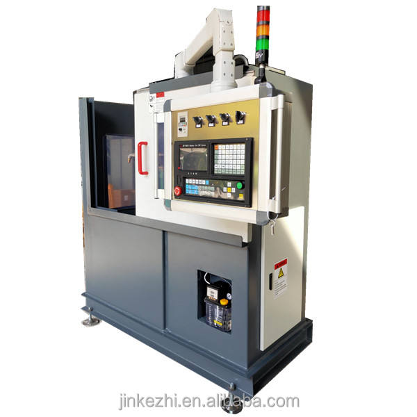
Featured Product: CNC Induction Hardening Scanner on MEGA BDM
MEGA BDM has sourced and verified the CNC Controlled Induction Hardening Scanner for Shafts, Gears, and Industrial Components from a verified global heat treatment equipment manufacturer with proven induction hardening machine design, manufacturing, and international export experience across automotive, industrial, and general engineering applications.
👉 View the CNC Induction Hardening Scanner on MEGA BDM
Frequently Asked Questions
What power output and frequency does this machine have?
Confirm the power output (kW) and frequency (kHz) with the supplier for your component sizes and required case depths. Provide your shaft diameter range and target case depth for an accurate specification.
What is the maximum component length and diameter?
Confirm the maximum component length (center distance) and maximum diameter with the supplier. Provide your largest component dimensions to confirm the machine can accommodate them.
What quench medium is used?
Confirm the quench medium (water, polymer solution, or oil) with the supplier for your steel grades. Different steels require different quench severities — confirm the quench system is appropriate for your materials.
Can the machine harden gears as well as shafts?
Confirm gear hardening capability with the supplier. Gear hardening requires specialized coils (contour coils for tooth-by-tooth hardening or encircling coils for spin hardening) — confirm availability and cost of gear hardening coils.
What steel grades can be hardened?
Confirm compatible steel grades with the supplier. Generally, steels with 0.35%+ carbon content are suitable for induction hardening — provide your specific steel grades for confirmation.
What after-sales support and spare parts are available?
Confirm the supplier’s after-sales support, spare parts availability (particularly induction coils and power supply components), and remote troubleshooting capability. Induction coils are wear items — confirm availability and cost.
Conclusion
The CNC Controlled Induction Hardening Scanner brings precision surface heat treatment in-house — eliminating the cost, delay, and quality uncertainty of outsourced hardening while delivering CNC-controlled repeatability that manual hardening machines cannot match.
At $17,000 — with payback periods of 2 weeks to 7 months depending on production volume and outsourcing cost savings — this machine is one of the highest-ROI capital investments available in precision component manufacturing. For automotive parts manufacturers, gearbox producers, shaft and axle manufacturers, and general engineering job shops that currently outsource induction hardening, bringing this process in-house with a CNC-controlled scanner is a straightforward decision with compelling economics.
The combination of scanning hardening technology for long components, CNC precision control for repeatable results, and integrated quenching for optimal metallurgical outcomes makes this machine a complete, professional-grade induction hardening solution for the full range of shaft, gear, and rotating component applications.
👉 View the full product details on MEGA BDM